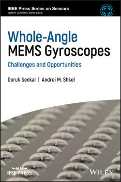
Whole-Angle MEMS Gyroscopes

Реклама. ООО «ЛитРес», ИНН: 7719571260.
Оглавление
Doruk Senkal. Whole-Angle MEMS Gyroscopes
Table of Contents
List of Tables
List of Illustrations
Guide
Pages
Whole-Angle MEMS Gyroscopes. Challenges and Opportunities
List of Abbreviations
Preface
About the Authors
1 Introduction
1.1 Types of Coriolis Vibratory Gyroscopes
1.1.1 Nondegenerate Mode Gyroscopes
1.1.2 Degenerate Mode Gyroscopes
1.2 Generalized CVG Errors
1.2.1 Scale Factor Errors
1.2.2 Bias Errors
1.2.3 Noise Processes
1.2.3.1 Allan Variance
1.3 Overview
2 Dynamics. 2.1 Introduction to Whole‐Angle Gyroscopes
2.2 Foucault Pendulum Analogy
2.2.1 Damping and ‐factor
2.2.1.1 Viscous Damping
2.2.1.2 Anchor Losses
2.2.1.3 Material Losses
2.2.1.4 Surface Losses
2.2.1.5 Mode Coupling Losses
2.2.1.6 Additional Dissipation Mechanisms
2.2.2 Principal Axes of Elasticity and Damping
2.3 Canonical Variables
2.4 Effect of Structural Imperfections
2.5 Challenges of Whole‐Angle Gyroscopes
3 Control Strategies
3.1 Quadrature and Coriolis Duality
3.2 Rate Gyroscope Mechanization
3.2.1 Open‐loop Mechanization
3.2.1.1 Drive Mode Oscillator
3.2.1.2 Amplitude Gain Control
3.2.1.3 Phase Locked Loop/Demodulation
3.2.1.4 Quadrature Cancellation
3.2.2 Force‐to‐rebalance Mechanization
3.2.2.1 Force‐to‐rebalance Loop
3.2.2.2 Quadrature Null Loop
3.3 Whole‐Angle Mechanization
3.3.1 Control System Overview
3.3.2 Amplitude Gain Control
3.3.2.1 Vector Drive
3.3.2.2 Parametric Drive
3.3.3 Quadrature Null Loop
3.3.3.1 AC Quadrature Null
3.3.3.2 DC Quadrature Null
3.3.4 Force‐to‐rebalance and Virtual Carouseling
3.4 Conclusions
4 Overview of 2‐D Micro‐Machined Whole‐Angle Gyroscopes
4.1 2‐D Micro‐Machined Whole‐Angle Gyroscope Architectures. 4.1.1 Lumped Mass Systems
4.1.2 Ring/Disk Systems
4.1.2.1 Ring Gyroscopes
4.1.2.2 Concentric Ring Systems
4.1.2.3 Disk Gyroscopes
4.2 2‐D Micro‐Machining Processes
4.2.1 Traditional Silicon MEMS Process
4.2.2 Integrated MEMS/CMOS Fabrication Process
4.2.3 Epitaxial Silicon Encapsulation Process
5 Example 2‐D Micro‐Machined Whole‐Angle Gyroscopes
5.1 A Distributed Mass MEMS Gyroscope – Toroidal Ring Gyroscope
5.1.1 Architecture
5.1.1.1 Electrode Architecture
5.1.2 Experimental Demonstration of the Concept. 5.1.2.1 Fabrication
5.1.2.2 Experimental Setup
5.1.2.3 Mechanical Characterization
5.1.2.4 Rate Gyroscope Operation
5.1.2.5 Comparison of Vector Drive and Parametric Drive
5.2 A Lumped Mass MEMS Gyroscope – Dual Foucault Pendulum Gyroscope
5.2.1 Architecture
5.2.1.1 Electrode Architecture
5.2.2 Experimental Demonstration of the Concept. 5.2.2.1 Fabrication
5.2.2.2 Experimental Setup
5.2.2.3 Mechanical Characterization
5.2.2.4 Rate Gyroscope Operation
5.2.2.5 Parameter Identification
6 Overview of 3‐D Shell Implementations
6.1 Macro‐scale Hemispherical Resonator Gyroscopes
6.2 3‐D Micro‐Shell Fabrication Processes
6.2.1 Bulk Micro‐Machining Processes
6.2.2 Surface‐Micro‐Machined Micro‐Shell Resonators
6.3 Transduction of 3‐D Micro‐Shell Resonators
6.3.1 Electromagnetic Excitation
6.3.2 Optomechanical Detection
6.3.3 Electrostatic Transduction
7 Design and Fabrication of Micro‐glassblown Wineglass Resonators
7.1 Design of Micro‐Glassblown Wineglass Resonators
7.1.1 Design of Micro‐Wineglass Geometry
7.1.1.1 Analytical Solution
7.1.1.2 Finite Element Analysis
7.1.1.3 Effect of Stem Geometry on Anchor Loss
7.1.2 Design for High Frequency Symmetry
7.1.2.1 Frequency Symmetry Scaling Laws
7.1.2.2 Stability of Micro‐Glassblown Structures
7.2 An Example Fabrication Process for Micro‐glassblown Wineglass Resonators
7.2.1 Substrate Preparation
7.2.2 Wafer Bonding
7.2.3 Micro‐Glassblowing
7.2.4 Wineglass Release
7.3 Characterization of Micro‐Glassblown Shells
7.3.1 Surface Roughness
7.3.2 Material Composition
8 Transduction of Micro‐Glassblown Wineglass Resonators
8.1 Assembled Electrodes
8.1.1 Design
8.1.2 Fabrication
8.1.2.1 Experimental Characterization
8.2 In‐plane Electrodes
8.3 Fabrication
8.4 Experimental Characterization
8.5 Out‐of‐plane Electrodes
8.6 Design
8.7 Fabrication
8.8 Experimental Characterization
9 Conclusions and Future Trends
9.1 Mechanical Trimming of Structural Imperfections
9.2 Self‐calibration
9.3 Integration and Packaging
References
Index. a
b
c
d
e
f
g
h
i
l
m
n
o
p
q
r
s
t
u
v
w
x
IEEE Press Series on Sensors
WILEY END USER LICENSE AGREEMENT
Отрывок из книги
IEEE Press 445 Hoes Lane Piscataway, NJ 08854
.....
where is the measured gyroscope output, corresponding to total angular read‐out, including the actual angle of rotation, errors in scale factor, bias, and noise.
Scale factor (or sensitivity) errors represent a deviation in gyroscope sensitivity from expected values, which results in a nonunity gain between “true” angular rate and “perceived” angular rate. Scale factor errors can be caused by either an error in initial scale factor calibration or a drift in scale factor postcalibration due to a change in environmental conditions, such as a change in temperature or supply voltages, application of external mechanical stresses to the sensing element, or aging effects internal to the sensor, such as a change in cavity pressure of the vacuum packaged sensing element.
.....