Читать книгу Applications of Polymer Nanofibers - Группа авторов - Страница 25
1.6.2 Porous Fibers
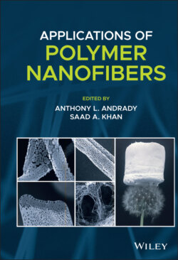
ОглавлениеPorous electrospun nanofibers (Figure 1.5) are of increasing interest in filtration, energy storage, tissue engineering, and catalysis (Li and Xia 2004; Katsogiannis et al. 2016; Wei et al. 2013; Natarajan et al. 2014; Hou et al. 2014). The pores increase surface area of the fibers (Katsogiannis et al. 2016; Natarajan et al. 2014). In tissue engineering, porous scaffolds better mimic extracellular matrix and improve cell attachment (Katsogiannis et al. 2015, 2016).
Figure 1.5 Overview of advanced electrospun nanofiber cross sections: (a) porous fibers
(Source: Dayal et al. (2007).),
(b, c) core–shell fibers
(Source: (b) Reprinted from Dicks and Heunis (2010). Copyright (2010). T.D.J. Heunis and L.M.T. Dicks;
(c) Reprinted from Jalaja et al. (2016), Copyright (2015), with permission from Elsevier.),
and (d, e) nanochannels
(Source: Zhao et al. (2007)).
One approach to making porous nanofibers is electrospinning multicomponent fibers and selectively leaching one of the components (Wei et al. 2013; Gupta et al. 2009). For example, polycaprolactone and sodium chloride can be electrospun from a solvent mixture of methanol and chloroform. The subsequent fibers were submerged in water to selectively dissolve the salt to produce porous fibers (Wang et al. 2009). Polymers have also been used as porogens (Wei et al. 2013) and lead to interconnected pores throughout the fiber. Leeching of salt with water is advantageous because it avoids introducing toxic substances into the system (Hou et al. 2014). However, the salt may not be fully mixed resulting in uneven pore sizes and distributions. Further, this method is time‐consuming as complete leeching of the salt can sometimes be difficult (Wei et al. 2013).
Porous fibers can also be achieved during electrospinning by inducing phase separation (Dayal et al. 2007; Dayal and Kyu 2006). Several variations for inducing phase separation have been explored including TIPS/vapor‐induced phase separation (VIPS) in which water condenses on the surface of the fibers as the solvent evaporates and reduces temperature leading to pores (Natarajan et al. 2014), and nonsolvent‐induced phase separation (NIPS) in which solvent mixtures are used to induce phase separation (Dayal and Kyu 2006). In NIPS, a mixture of solvents of varying volatilities is used. In this approach, the electrospinning solution is a stable, one‐phase system. As solvent evaporates and the polymer concentration increases, the system traverses across the metastable and unstable, two phase region of the phase diagram. Liquid–liquid phase separation into a polymer‐rich phase and a polymer‐poor phase occurs by spinodal decomposition or nucleation and growth. The polymer‐rich phase secures the bulk foundation of the fiber. With further increase in polymer concentration, an interconnected pore structure forms due to spinodal decomposition in the unstable, two‐phase region. The interconnected pore structure becomes the porous fiber as the polymer poor phase evaporates. The porous fibers tend to form if the polymer/solvent system is partially miscible with an upper critical solution temperature envelope at the electrospinning temperature (Dayal et al. 2007; Dayal and Kyu 2006).
Electrospinning process parameters can affect the properties of the porous fiber, i.e. fiber diameters, pore diameters, and pore distributions. Katsogiannis et al. postulate that increasing the tip‐to‐collector distance increases the percentage of area covered with pores due to increased solvent evaporation. Experimentally, the area percent of fibers covered in pores could be increased from 10% to 30% by increasing the tip‐to‐collector distance. Increasing the voltage also increased the pore area from ~10% to 20–45% which was attributed to the voltage increasing the rate of stretching and solvent evaporation. Increasing the flow rate also increased the area percent covered in pores (Katsogiannis et al. 2016). Pore size and distribution is affected by polymer solution properties, namely, the molecular weight of the polymer. The relative humidity of the environment also affects pore size and distribution. For example, Natarajan et al. increased the humidity from 30% to 70% and observed the average pore size of polylactic acid (PLA) fibers to increase from 85 to 135 nm. A relative humidity above 30% was required to observe porous fibers (Natarajan et al. 2014).
Foam‐assisted electrospinning is another single‐step method to produce mesoporous fibers. A PVP template, with titanium precursor and foaming agent diisopropyl azodiformate are electrospun using ethyl alcohol and acetic acid as the solvents. The release of vapor from the foaming agent created pores throughout the polymeric precursor fibers. The fibers were subsequently calcined to achieve mesoporous TiO2 fiber (Hou et al. 2014).