Читать книгу Chevy Differentials - Jefferson Bryant - Страница 9
На сайте Литреса книга снята с продажи.
ОглавлениеCHAPTER 2
SUSPENSION TYPES AND DIFFERENTIAL HOUSINGS
General Motors has been using variations of the 10- and 12-bolt differential since the mid-1960s so many different housings are in use. The basic 10-bolt has been used in every type of vehicle, for both rear and front (four-wheel drive) applications. The 12-bolt passenger car design was relatively short lived, with an eight-year run, but the truck version ran through the late 1980s, so many vehicles use those.
GM differential housings have used several types of mounting styles, including leaf springs, coil springs with trailing arms, coil springs with a triangulated four-link, and independent rear suspension (IRS). Front differentials are either leaf springs or independent front suspension (IFS). Some housings can be converted to another suspension system while others cannot; it just depends on the design of the suspension, particularly in the case of four-link rear systems. You can adapt a four-link housing to a leaf spring car, but it requires so much fabrication that it is not practical to install a leaf spring housing to a four-link.
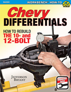
To start the disassembly of the differential, first you remove the center cover. You can clearly see the ring gear and carrier, which contains the limited-slip clutch pack. In a typical high-mileage rebuild, you need to replace most of the bearings, gaskets, and seals.
Leaf Spring Rear Suspension
A leaf spring mounting system uses a pair of arched steel or fiberglass leaf packs to suspend the rear housing from the frame. The leaf packs are typically made up of multiple leaves, but in some cases, these are single-leaf springs. The leaves use two mounting points to the chassis in the front and rear of the housing itself.
The housing may be mounted above or below the leaf springs. The housing is below the springs in most trucks for added ride height, and is called overslung. The housing is typically underslung, or mounted below the spring pack, in most passenger cars, and lowers the ride height.
The leaf spring rear suspension is fitted to Camaros, Novas, trucks, and several other vehicles. This leaf spring Chevy truck has an overslung housing (the housing is positioned underneath the springs).
Older pre-1968 Chevy and GMC trucks have a long trailing-arm setup like this. They used a large coil spring. For heavy loads a half-leaf overload spring was optional.
Leaf springs can suffer from axle wrap. Under heavy acceleration, the rear springs twist up against the forward rotation of the tires. As the housing rotates, the leaf springs contort against their natural arch. The front of the leaf rises and allows the housing to rotate. When the leaf spring cannot wrap any more, it snaps back into its natural state and shocks the tires. Unfortunately, this often happens several times. Once the wrap and snap has occurred, it tends to become a cycle. The rear wheels jump up and down and the rear of the vehicle starts bouncing up and down. Hence you get the term: “wheel hop.” This results in a dangerous loss of control and so it must be remedied.
Trucks are more susceptible to this condition because beds are light and do not place much weight on the axle unless there is something in the bed. If you punch the gas and the back end starts hopping, you have to let up on the gas to stop it.
Installing traction bars is an effective fix for wheel hop. They bolt to the housing mount under the leaf pack and extend forward to the front leaf spring mount. As the housing tries to rotate upward on heavy acceleration, the bar contacts the front mount, locking the leaf spring in shape so that it can’t wrap, and thereby eliminating the effect of wheel hop. Different versions of these devices are available, but the principle is the same with each.
Watt’s Linkage Rear Suspension
When torque is applied to a leaf spring suspension design, it has a tendency to walk from side to side. This is due to the rubber bushings, the way the rear of the springs are mounted with two hanging shackles, and the multiple leaves. Leaf spring suspensions have certain drawbacks. When a leaf spring car enters a corner, the entire leaf pack compresses and can fan out slightly, just like a deck of cards.
In addition, leaf spring shackles and bushings can flex so suspension actuation is sloppy. As a result, handling deteriorates and it becomes difficult to negotiate corners at higher speeds.
One of the better solutions for this problem is a Watt’s linkage, which connects both sides’ leaf packs with an articulating arm in the center to keep the housing from wandering from side to side under heavy loads. These work extremely well and are often used in road race vehicles.
Originally designed by James Watt in 1784, the linkage was intended for the Watt steam engine. Also referred to as parallel motion, the Watt’s linkage prevents side-to-side movement by providing a solid location at the center of the vehicle. The propeller is mounted in the center of the vehicle on a bracket that is attached to the chassis. The two side arms connect to the propeller, which rotates as the suspension moves up and down. This allows free vertical movement, but positively locates the housing in the center of the car.
Coil Spring Rear Suspension
This is the more versatile form of rear suspension because it provides a lot of tuning latitude. A coil spring is not susceptible to axle wrap because every coil spring rear suspension uses solid bars to connect the housing to the chassis. Two main types of factory links are used with 10- and 12-bolt designs: trailing arms and the triangulated four-link.
Some 1960s and 1970s GM cars are not equipped with the common Chevy 10- or 12-bolt axle assemblies. This means that you need to positively identify the axle assembly before you begin work. The GM B-Body cars, such as the Impala and Caprice, used a version of the four-link system, but it is a little more complicated than the A- and G-Body versions. This 1962 Buick used an oddball differential that’s unrelated to the 10 or 12-bolt, but the suspension is the same. This one uses a panhard bar as well.
Trailing Arm Axle
A trailing arm is a long bar that runs from the forward portion of the chassis to the rear where the housing is mounted. Trailing arms are typically used in an underslung axle assembly. Trailing arm axles are commonly found on GMC and Chevy trucks built from 1960 through 1968.
This design works well because the trailing arms are quite long. Their front pivot point is in the center of the chassis, so it yields excellent handling characteristics. The drawback for this design is that coil springs simply cannot handle extreme loads.
For this reason, coil springs are not often used for the rear suspension of trucks. The factory fix was a half-leaf overload spring, but that did not solve the tramping, or wheel-hop, conditions until they converted to a leaf pack in the late 1960s.
Passenger cars from the early 1960s often had the trailing arm design too, including the GM X-frame B-Body cars (Impala, Biscayne, etc.), but these cars don’t have 10- or 12-bolt differentials.
The coil spring in most trailing arm designs is positioned on the trailing arm itself, so it connects to a spring pad on the frame. This can make for some awkward spring angles on the car versions, but trucks use longer springs that sit vertical. One of the nicer aspects of working on a trailing arm vehicle with the spring on the arm is that you don’t have to disconnect the suspension to remove the housing.
Panhard Bar Axle
The panhard bar is a long bar that connects one side of the housing to the opposite side of the chassis with only two bars and one chassis mount per bar. The trailing arm design needs to locate the housing to the center of the chassis, and the panhard bar connects to the housing in the center of the chassis. In stock form, this bar is solid and not adjustable. Adjustable upgrades are available from the aftermarket.
With a panhard bar, the vertical motion of the axle is more controlled; however, it swings to one side in a slight arc. This is due to the fact that the bar cannot change length; the housing must move along this arc to facilitate the vertical movement.
The longer the bar, the shallower the arc; therefore the less the side movement. Because of this, a panhard bar is much less effective on passenger cars than trucks. The bar is too short to effectively control the horizontal location and keep the tires from contacting the fender wells. General Motors installed these bars on many of its cars in the early 1960s, and they have lots of space between the tires and the wheel lips because of it.
In addition, you cannot correct the suspension geometry and reduce the arc of travel. The only way to do that is to remove the panhard bar and convert to a Watt’s linkage design.
Triangulated Four-Link Rear Suspension
When the muscle car era began, General Motors introduced its rear suspension version: the triangulated four-link. This design incorporates a pair of lower bars that run in-line with the chassis, and two very short upper arms that angle toward the center of the car at the top of the chassis. All four bars connect to different points on the housing. The lowers are on one plane while the uppers are on another plane. The goal is to maintain a singular vertical range of motion. It’s also designed to eliminate the possibility of the housing wrapping up under acceleration and to reduce side-to-side deflection with the angled upper bars.
The type of Chevy 10- and 12-bolt axle housing depends on the style of suspension. This GM A-Body frame uses the triangulated four-link system, so this housing fits only a GM A-Body car with this four-link system. This frame is also used on GM G-Body cars, though it is not a direct swap.
When a Chevy 10- or 12-bolt is pulled from a vehicle, it often looks like this but it may be even more greasy, grimy, and possibly rusty. Years of road grime pile up on the differential housing. So the first step is to strip it all away. The most common way to clean it is with a liberal coating of oven cleaner or engine degreaser, and then power wash it. If the axle housing is particularly rusty, you may need to media blast it after your initial degreasing.
It’s about the best factory suspension there is. The aftermarket equivalent is virtually identical in nature, and the triangulated upper bars are what set it apart from all the rest. These bars resist side-to-side movement because of the inward angle. This design eliminates the need for a panhard bar to keep the axle assembly from wandering side to side. However, this does not mean it is without fault.
In stock form, the bars with simple U-shaped channels can bend and twist under extreme use. Although the large rubber bushings provide an excellent ride, they are too soft and spongy for high-performance driving. Aftermarket upgrades include polyurethane bushings or even bearing conversions, and adjustable upper arms allow tuning of the pinion angle. Solid or tubular lower bars are another popular upgrade. The factory bars can be upgraded on the cheap by boxing them in. A plate is added to the open side of the channel, reinforcing the bars so that they do not bend or flex.
The axle housings for four-link suspensions have these upper bushings; this type of suspension is found on A- and G-Body cars. There is no easy way to remove these bushings and after years of use they are often worn or damaged. The best method is to use an air impact hammer and a chisel to crush the bushing end and then drive it out.
Once you have thoroughly cleaned the axle assembly, you should protect the surfaces. If you have stripped it down to the metal, it starts collecting surface rust immediately. So, it’s a good idea to paint the axle assembly to prevent rust from forming and to make it look fresh. A new coat of paint makes a housing look much better than a crusty, greasy one. If you’re not set up to paint it, you should coat it with WD-40 or some other lubricant to prevent rust from forming.
The springs are typically mounted to the housing for four-link suspensions, which makes removing them quite easy. The upper mounts are cast into the center section of the housing, which is a problem if you are looking to upgrade to a 12-bolt unit. You can’t just weld mounts to the housing as you can with a leaf spring or trailing arm unit. Instead, you need to find either a factory 12-bolt housing or purchase an aftermarket version.
Independent Rear Suspension
The Corvette is the only regular production vehicle General Motors made that carried independent rear suspension. The 1963 through 1978 Corvettes were fitted with axles similar to the 10- and 12-bolt, but not exactly the same. However, conversions are available that use 12-bolt differentials in the C2 and C3 Corvette housing. Although a solid axle system is used in conjunction with a multi-link and leaf spring suspension system, an IRS system uses an independent axle shaft on each side, so both rear wheels can move independently according to road conditions and load on the suspension. The Corvette design, however, uses a transverse-mounted fiberglass mono-leaf spring, and that connects both sides of the axle.
Project: Building a Universal Axle
A universal axle is an indispensable tool when fitting a rear axle assembly to a vehicle (and it has several other uses). If you build many project cars and need to move them around, this is a good tool for you. How often do you wish you had a rolling axle that is adjustable for width and fits under anything? Although your initial answer may be “never,” you might be surprised just how often this rig comes in handy, especially if you buy/build a lot of project cars. This universal axle can be used as a custom rear-end jig, trailering axle, and car body mover.
I first discovered the universal axle during a drag car build. My axle builder, Harold Evans of Perkins, Oklahoma, designed and built this adjustable axle so we could set up the rear of the drag car to fit with the wheel and tire combo, and he used it as a jig to build the narrowed housing. With that accomplished, I have this heavy-duty axle that expands from 45-inch to 65-inch with the turn of a couple bolts, and it has multiple bolt patterns for whatever wheels are needed.
You need a few spare parts for this project. I used pieces from a mid-1960s Chevy truck, but you can use whatever you have available. If you have to buy the parts, they are typically available on Craigslist or at a salvage yard. Drum-brake front spindles are easy to find and super cheap.
Here is the basic parts list:
• Drum brake spindles and hubs: Bolt pattern only matters if you are setting it up to use a specific wheel. I drilled mine for 5-on-4.75-inch, the most common GM pattern, plus I left the six-bolt pattern.
• Square tubing: You need two sizes. One is for the outer section and one is for the sliding inner section. I used 3-inch mild steel for the outer and 2.5-inch mild steel for the inner. The tubing was about 1/4-inch thick, strong enough to hold up the back end of a car.
• A good welder and the ability to cut the tubing square. If you don’t have a metal bandsaw, you can have the steel shop cut it to size for you.
• Four nuts and bolts: A couple pairs of 1/2-inch nuts with 2-inch-long bolts lock the width of the axle.
The project is not complicated or extremely labor intensive so you can probably build it in a day. My machinist went the extra mile by fly-cutting the spindles on a lathe, but that is not absolutely necessary. Once you have one of these adjustable axles, you will find all kinds uses for it.
Wheel and Axle Fitment on Chassis
This project installs a tubular A-Body suspension. First, you need to build a dummy axle for suspension and axle fitment purposes. I used a set of drum spindles from a 1960s Chevy truck that had been converted to discs. You can also use late-model 4×4 front hubs, mid-1990s on up half-ton trucks work great. You can check with local shops for late-model 4×4 front hubs because they are frequently replaced. The bearings don’t have to be in great shape for this tool.
Disassemble Drum Brakes
You disassemble the drum brakes to create the tool. Rivets often hold the drums to the hub; drill them out. I removed the cotter pin and castle nut that holds the rotor and hub on the spindle.
Remove Retention Bolts
With the drum and rotor removed, the bolts holding the steering arms can be accessed. Use a socket and ratchet or wrench to remove the retention bolts.
Remove Steering Arm
Once the steering arm has been removed, the bolts can come out. The steering arm is held on with two fine-thread nuts and bolts.
Remove Splash Shield
Sometimes the splash shields and bearings are difficult to remove, so I set the splash shield on the bench and smacked the shaft with a hammer. I positioned a length of steel stock on the end of the spindle and gave it some firm taps with a dead-blow hammer. If you need to use a hammer, protect the spindle threads. If you damage the threads, the castle nut won’t thread back on.
Remove Cover
To separate the cover from the hub, you need to drill out the rivets on the cover. If necessary, use a punch and a hammer to knock them out.
Cut Bracket Off Spindle
Once the cover has been removed and the spindle has been separated, you can cut the bracket off the spindle because you only need the spindle and the rotor to perform this procedure.
Cut Off Bracket
To make the tool easier to use, you can cut off the bracket. Most mechanics use a reciprocating saw. In this case, the machinist used a band saw to cut off the top half of the spindle.
Clean Up Spindle
The backside of the spindles need to be flat to weld the spindle to the square steel tube. In addition, the width of each spindle should be the same so the measuring and fitment process is easier. You can use an angle grinder to clean up the spindle. One of the benefits to being in a machine shop is that the machinist can turn down the back of the spindle in a metal lathe for a flush fit.
Inspect Spindle
Your spindle should look similar to this. You want the back of the spindle to have enough surface area to easily weld it to the dummy axle. With a lathe, it only took about four minutes to do this portion.
Position Spindle Against Tubing
Position the spindle flush against the 3-inch square tubing; the spindle needs to be square against this tube to achieve accurate measurements. The spindle needs to be accurately machined flat. If the axle is for sizing custom rear differential housings, the wheel needs to roll true and not wobble.
Weld Spindle to Axle Tube
You can use a MIG welder to weld the top and bottom of the spindle to the square axle tube.
Inspect Axle Tube
The dummy axle tube has an extendable end tube on one side so it can be used for mocking up the axle width on different vehicles. It slides over the end and four bolts tighten to hold it in place. The center section is made of a section of 2.5-inch tubing welded inside one half of the 3-inch tubing.
Inspect Axle Tube (CONTINUED)
These bolts lock the extendable tube into the proper position so accurate sizing can be attained.
Drill and Tap Rotors
Drill and tap the rotors for the 5-on-4.75-inch bolt pattern. Use a set of bolts, rather than studs because studs would limit you to one bolt pattern. This axle was put to use in a drag car, setting up the rear suspension and width for the custom housing.
Roll Dummy Axle Under Car
Install the wheels on the hubs and roll the dummy axle assembly under the car. At this stage, you can precisely measure width and take several height measurements. The key measurements are ride height, overall width, space between the tires and inner fenders and outer fenders, as well as squareness in the chassis. With accurate ride height and width measurements, you can order the correct rear housing for this project. After this project, you can also use the axle to move a project car whose rear differential has been previously liberated from the chassis.
Measure Ride Height
Use a level and tape measure to measure the desired ride height for the car. You are looking for about 8 inches of space between the axle centerline and the top of the wheel arch. Both sides need to match. This helps determine the correct width and clearance for the new rear-end housing.
Front Suspension
Two types of suspension can be found up front: leaf or IFS. You can certainly swap the front housing for either one, but the 10-bolt version was only used in leaf spring trucks.
Just as with the rear leaf design, the front leaf in trucks is oversprung, so it’s easy to add clearance with a block lift. At the place where the axles come out of the ends, steering knuckles on the front housing connect to the wheel hub though a U-joint. The axle itself has a yoke on the end that holds one side of the U-joint, and the wheel hub connects to the other. This allows the steering knuckle to articulate. Newer four-wheel-drive trucks use constant velocity (CV) joints instead for longer life.
The 8.5-inch 10-bolt front axles were used from 1977 through 1991. When the GM 8.25-inch differential was introduced, the company used a completely different independent front suspension design. GM trucks with IFS use a design that is not similar to the 10- and 12-bolt differential.
Advanced Suspension Components
On classic GM cars and trucks, the rear suspension cradles the Chevy 10- or 12-bolt axle assembly and therefore, it plays a pivotal role in application of power to the ground as do the components inside the housing itself. To restore the original ride and handling, you can simply replace the stock bushings with rubber or poly-graphite bushings. But vintage muscle cars have antiquated handling and suspension performance. Even some modern compact cars can corner better than most of our preferred classic muscle. If you want to carve corners and put more power to the ground, a more substantial change is necessary. Many aftermarket companies offer suspension solutions, including Heigts, Chassisworks, Art Morrison, and Detroit Speed for classic GM rear-wheel-drive cars.
Global West Systems
Global West offers two lines of advanced suspension components: the Negative Roll and G-Plus. The Negative Roll system is the more advanced of the two. It requires tall spindles and delivers superior performance. But it is designed for road race applications and can be a little harsh on the street.
For most street-driven applications, the G-Plus system is the better option, offering performance and versatility in one complete kit. The G-Plus system can be used with stock, 2-inch-drop, or ATS spindles. It also works with most stock-style spindles, so almost any braking system can be used. I opted for a Global West system for the Buick. This kit includes the choice of using coil springs or coil-over shocks. Although the Global West coil springs are certainly capable of a quality ride,
I opted for the adjustability and control of the coil-over shocks. Global West uses QA-1 shocks with coil-over springs exclusively. Many consider these to be the best in the industry. I selected the double-adjustable shocks, which have 24 settings each for rebound and compression. These shocks offer 576 tuning options, which might seem intimidating at first, but after becoming familiar with the settings, they are easy to use and adjust.
I initially set up the system with all four shocks in the middle at 12 clicks. The car rode somewhat firm, but it certainly felt as if I were in control. I wanted a low ride height to accentuate the new Centerline Retro 17-inch billet wheels and Kumho Ecsta Supra rubber that provides the grip. The benefit of coil-overs is that you can run them high, low, or anywhere in between, so they’re the perfect solution for any performance ride.
My setup placed the 24.5-inch-tall tires about 1-inch from the inner fender, and as a result, there would never be enough clearance with a stock system. However, I had enough clearance and therefore no tire rubbing issues with the Global West kit with the exception of at the very end of the testing. During the final stint, I had the steering locked and suspension in full tilt; only a little rubbing occurred.
Sway Bar Upgrade
The 1971 Buick GS was going to be subjected to higher cornering speeds so a sway bar upgrade was in order. I installed an Addco 1⅛-inch front and a 1-inch rear sway bar. Global West also offers factory-size sway bars, making it a simple package purchase. A common mistake when choosing sway bars is to go too large. A sway bar that’s larger than necessary creates more handling problems than it solves. It pulls the inside tire off the ground in a hard corner. Corner entry understeer and corner exit oversteer are just a couple of the problems caused by using sway bars that are too big. Global West does not suggest using a 1¼-inch sway bar with their suspension systems for the GM A-body.
The installation is quite simple and it took less than a weekend to complete. Fitting new components requires more than one set of hands and helpers always make things go a little faster. You need a few tools: a pickle fork to remove the ball joints and an impact gun to remove rusted nuts and bolts.
Handling Improvement
All of the modifications dramatically improve the handling of the car. Not only is cornering improved, but straight-line performance and braking are improved as well. To quantify the improvements, I performed some skid-pad testing using a Vericom VC3000 testing computer.
This computer uses horizontal and lateral accelerometers to measure G-forces and complex formulas to calculate the results. The Vericom is the most accurate data-logging computer of its kind, and the company kindly loaned one to me.
To perform a skid pad test, the car is driven in a large circle, at a steady pace. As each round is completed, the circle is turned tighter and tighter as well as faster and faster. As soon as the rear tires begin to slip, the G-forces are recorded. This is the amount of lateral force that a suspension can handle.
In stock form, the GS recorded .671 G on the skid pad, which is certainly respectable handling. With the G-Plus suspension installed (very little setup was required), the Buick GS convertible pulled 1.04 Gs, which was a vast improvement. At 1 G, you really feel the cornering forces and it was very difficult to make the rear slide under consistent power. Of course, with more than 400 horses on tap, a quick mash of the pedal would certainly get things hairy pretty quickly.
Under hard cornering, the GS now sticks hard to the road and feels like it’s on rails. The steering is tighter with the improved geometry. The bumps that used to send me bouncing out of the seat are now handled with ease, quite surprising considering the extremely low stance I set for the coil-over springs.
Once the car is done, I plan on hitting a couple of open-track days to see how capable the GS really is. Until then, the back roads will just have to do.
Project: Installing an A-Body Axle with Tubular Arms
Stock control arms (top) are made of stamped steel and they flex and deflect, changing the geometry of the suspension when under load. The aftermarket tubular control arms (bottom) are made of high-strength steel alloy; but more important, the tubular design provides much greater strength over the stock control arms. In addition, the tubular arms afford adjustability to the suspension for particular street or competition conditions. The uppers are adjusted to match the factory length.
Inspect Control Arm
Global West makes control arms for a variety of makes and models. They are far stronger and provide far better suspension performance than the stock stamped steel arms. The lower arms (shown) feature Delrin bushings and use bearings instead of polyurethane or rubber bushings to eliminate side-to-side deflection in the suspension.
Fit Arm to Bracket
The upper control arms are fitted to the chassis brackets, secured with the new hardware and are allowed to hang free.
Inspect Strut Rod
The lower arms feature an adjustable strut rod, which puts preload on the chassis mounts. One side bolts to the frame in the factory strut location.
Locate Frame Mount
Each lower arm is installed to the factory mount in the frame. Note the position of the strut rod.
Bolt Arm and Rod Together
The kit comes with new hardware for all of the components. The lower arms and strut rod are bolted together, but not torqued until the weight of the car is on the suspension.
Position Axle Assembly
At this stage, you need to get a friend or helper to help move the axle assembly onto a floor jack. With the axle on a floor jack, you can move it into position, then raise or lower it. This allows you to attach the suspension links and ultimately complete the installation of the axle assembly. To facilitate the upper-mount installation, attach the upper suspension links to axle housing first. The upper mounts are tight, so this is the easiest way to get them on.
Connect Arm to Chassis Mounts
Next, raise the housing with a floor jack so the lower arm can be connected to the chassis mounts. Slip the bolts through the suspension arm ends and housing mounts.
Connect Springs to Housing and Frame
The springs lock onto a stub on the housing and the frame. There is plenty of room for them. Simply position the springs onto the spring nipples on the upper and lower platforms, and raise the housing until the weight of the car is on the springs. Install the shocks onto the upper and lower studs and torque the nuts to the specs provided in the kit.
Torque Bolts to Spec
With the rear at ride height (the weight of the car should be on the suspension), torque all of the bolts to spec. Use a quality torque wrench. The factory torque specs are 80 ft-lbs for each control arm bolt, 12 ft-lbs for the upper shock bolt, and 65 ft-lbs for the lower shock mount. Keep in mind that aftermarket kits may have different torque specs and you need to follow the aftermarket manufacturer’s instructions.
Project: Updating Inside the Housing
There is more to an axle assembly than just the differential and gears. The housing needs to be inspected, evaluated, and replaced if necessary. Even if you are only changing gear ratios, now is a good time to update the consumables inside the housing. All GM 10- and 12-bolt housings have six sets of bearings and races: two wheel bearings, two for the carrier, and two for the pinion. Although I cover the pinion-and-carrier bearings in Chapter 5, this project starts with the wheel bearings and the races for the pinion bearings. These are installed into the housing itself.
Remove Bearings from Center Section
You have two methods for removing the bearing races from the center section. You can use a race driver and a hammer to drive the race from the case, or you can use a large socket that matches the diameter of the race. When using the socket method, you also need to use an extension and a long bar to drive it from the case.
Professional Mechanic Tip
Remove Bearings from Center Section (CONTINUED)
A bearing race puller has a driving end that fits securely in the race and an extension that threads onto the driving end. Using a bearing puller is the preferred and easier method. Put the socket and extension into the tube and properly align it with the bearing race. Make sure the socket is sitting square on the race.
Remove Bearings from Center Section (CONTINUED)
Insert the bar into the axle tube after the socket and extension.
Remove Bearings from Center Section (CONTINUED)
Align the bar inside the socket extension. The bar should be about level with the floor so the socket is squarely engaging the bearing race. Use a hammer to swiftly strike the end of the bar.
The front and then rear pinion races must be removed in this order. Steady the bar and squarely engage the race with the socket. You can use a deadblow hammer (shown) to drive out the race.
Critical Inspection
Inspect Bearing Race Bore
With the front race removed, you can see the inner race from the front side of the housing. Closely inspect for any abnormalities or damage. Differentials usually do not experience damage in this area.
Inspect Bearing Race
A typical Chevy 10- or 12-bolt rebuild kit has the correct-size bearing races for all bearing surfaces. Inspect them carefully because damage in shipping and defects in manufacturing can occur. Make sure the new race surfaces are clean and true. Installed properly, the axle shafts will perform at their best. Inspect the races before you install them and make sure you use the correct race for the bearing.
Install Outer Bearing Race
Properly align the race within the bore so it is square. Place the socket against the edge of the race and make sure it’s square as well. Use a hammer to tap against the edge of the race and methodically and carefully drive it into the bore until it is firmly seated in position.
Install Outer Bearing Race (CONTINUED)
You can feel that the race is fully seated. This is what it looks like when it is seated.
Install Inner Bearing Race
Correctly installing the inner race can be difficult because it tends to twist and not stay square in the bore. The case surrounding the bore adds a level of difficulty. When installing the race, use a hammer and socket to slowly and carefully drive it down until it is fully seated in the bore.
Bearings and Races
The race is the machined surface on which the bearing rides, and it’s a replaceable component that is usually matched to the bearing. You can reuse the race if the bearings have not failed or been overheated, but you should replace the races when you change the bearings. The pinion bearing races are pressed into the housing. The larger inner bearing is pressed in from the carrier side while the smaller outer pinion bearing is pressed in from the yoke side. Special bearing installation tools are available, but it can be done with a hammer and an appropriate socket.
Wheel bearings are internal bearings and do not have races. Therefore, the bearing is pressed into the axle tube, just inside of the end plate, and the bearings ride on the axle shaft itself. Three types of bearings are offered for axles: standard, repair, and sealed.
Standard Bearings
These typical bearings are found in the axle assembly and are encased in a simple housing as a retainer. They are pressed into the axle tubes and the axle slides through them. Gear oil must be used to sustain the bearing’s lubricity. A seal must be installed after the bearing in order to cap the housing.
Repair Bearings
The bearing surface of the axle could be galled and pitted if your wheel bearings are worn out or damaged, the housing is run without oil, or the bearings have been over-heated. The rear axle assembly will howl from the bearing noise and the bearings won’t last very long. You have two choices: replace the axle or change to a repair bearing. These bearings use an integral seal that is shorter than a traditional seal, allowing the new bearings to ride farther out on the axle shaft itself, where there is no damage. These bearings are expensive and they don’t always work, but it is an option.
Sealed Bearings
This type of bearing seals off the axle without a separate seal. They are used with C-clip eliminator kits for 10- and 12-bolt units. Because of the design, sealed bearings must be pressed onto the axle. They are very good for controlling up-and-down motion because they have no play in them, unlike the standard and repair bearings. However, they are also quite expensive. The sealed bearings for GM 10- and 12-bolts require the above-mentioned eliminator kit.
Many home workshops do not have a hydraulic press, but if you do, it allows you to precisely press the races into the housing. Here, the socket and extension are aligned under the press. The next step is to slowly engage the press and watch it press the race into the bore.
C-Clip Conversions
C-clip eliminators are required for certain race classes and are often used for high-horsepower applications and off-road vehicles because the wheels on the axle remain with the vehicle. If a C-clip axle breaks, it allows the corresponding wheel to come out from under the car, and that is a very dangerous situation.
A C-clip eliminator replaces the C-clip and provides a much more secure way to retain the axle: The bearings are pressed onto the axles. A plate captures the bearing and also the axle when it is bolted to the housing end. In most cases, installing these eliminators does not require machining the housing, but stock axles do require machine work to ensure that the bearing can be pressed onto the correct area for engagement.
C-clip eliminators are not the only conversion option. You can convert a 10- and 12-bolt axle assembly to a flange-style retainer. But this requires some fabrication work. You need to cut off the existing axle ends and weld new ends on the housing. Then you press on Ford 9-inch-style press-on bearing axles; you don’t need to install C-clip eliminators for a street application.
The Buick and Oldsmobile bolt-in axles are great for performance because there are no C-clips. Unfortunately, most GM 10- and 12-bolts do not have this option.
When the underside of the car is tight, using the rear cover may be easier than the front port. Not always though. Some aftermarket housings don’t have a side fill port, so the rear cover is the only option. With this car, a hose relocates the bottle above the axle housing.
Keep in mind, C-clip eliminators are bolted, not welded, to the axle tubes. As a result, the ends can (and often do) flex against the housing end during extreme use. Nothing will prevent the flexing; not the manufacturer of the ends, their thickness, or the material. It’s going to occur. When they flex, the bearings wear out the seals. Sometimes the seals take a few years to wear out, but usually, they wear out in about a year with regular street use.
Bolt-in C-clip eliminators are not really a good option for street cars. The best option for a street car build is welding on new outer wheel bearings and new axles. These 9-inch Ford ends are the best solution if C-clips do not work for your build.