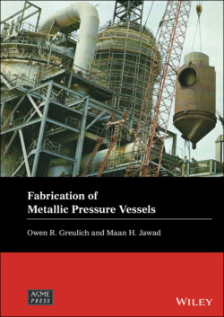
Читать книгу Fabrication of Metallic Pressure Vessels - Maan H. Jawad - Страница 2
Table of Contents
Оглавление1 Cover
2 Series Page
3 Title Page
4 Copyright Page
5 Dedication Page
6 Preface
7 Acknowledgments
8 1 Introduction 1.1 Introduction 1.2 Fabrication Sequence 1.3 Cost Considerations 1.4 Fabrication of Nonnuclear Versus Nuclear Pressure Vessels 1.5 Units and Abbreviations 1.6 Summary
9 2 Materials of Construction 2.1 Introduction 2.2 Ferrous Alloys 2.3 Nonferrous Alloys 2.4 Density of Some Ferrous and Nonferrous Alloys 2.5 Nonmetallic Vessels 2.6 Forms and Documentation 2.7 Miscellaneous Materials References
10 3 Layout 3.1 Introduction 3.2 Applications 3.3 Tools and Their Use 3.4 Layout Basics 3.5 Material Thickness and Bending Allowance 3.6 Angles and Channels 3.7 Marking Conventions 3.8 Future of Plate Layout Reference
11 4 Material Forming 4.1 Introduction 4.2 Brake Forming (Angles, Bump‐Forming) 4.3 Roll Forming (Shells, Reinforcing Pads, Pipe/Tube) 4.4 Tolerances Reference
12 5 Fabrication 5.1 Introduction 5.2 Layout 5.3 Weld Preparation 5.4 Forming 5.5 Vessel Fit Up and Assembly 5.6 Welding 5.7 Correction of Distortion 5.8 Heat Treatment 5.9 Post‐fabrication Machining 5.10 Field Fabrication – Special Issues 5.11 Machining 5.12 Cold Springing
13 6 Cutting and Machining 6.1 Introduction 6.2 Common Cutting Operations for Pressure Vessels 6.3 Cutting Processes 6.4 Common Machining Functions and Processes 6.5 Common Machining Functions for Pressure Vessels 6.6 Setup Issues 6.7 Material Removal Rates 6.8 Milling 6.9 Turning and Boring 6.10 Machining Centers 6.11 Drilling 6.12 Tapping 6.13 Water Jet Cutting 6.14 Laser Machining 6.15 Reaming 6.16 Electrical Discharge Machining, Plunge and Wire 6.17 Electrochemical Machining 6.18 Electron Beam Machining 6.19 Photochemical Machining 6.20 Ultrasonic Machining 6.21 Planing and Shaping 6.22 Broaching 6.23 3D Printing 6.24 Summary Reference
14 7 Welding 7.1 Introduction 7.2 Weld Details and Symbols 7.3 Weld Processes 7.4 Weld Preheat and Interpass Temperature 7.5 Post Weld Heat Treating 7.6 Welding Procedures 7.7 Control of Residual Stress and Distortion 7.8 Material Handling to Facilitate Welding 7.9 Weld Repair 7.10 Brazing Reference
15 8 Welding Procedures and Post Weld Heat Treatment 8.1 Introduction 8.2 Welding Procedures 8.3 Weld Preparation Special Requirements 8.4 Weld Joint Design and Process to Reduce Stress and Distortion 8.5 Weld Preheat and Interpass Temperature 8.6 Welder Versus Welding Operator 8.7 Weld Repair 8.8 Post Weld Heat Treating 8.9 Cladding, Overlay, and Loose Liners 8.10 Brazing Reference
16 9 Fabrication of Pressure Equipment Having Unique Characteristics 9.1 Introduction 9.2 Heat Exchangers 9.3 Dimpled Jackets 9.4 Layered Vessels 9.5 Rectangular Vessels 9.6 Vessels with Refractory and Insulation 9.7 Vessel Supports 9.8 Summary References
17 10 Surface Finishes 10.1 Introduction 10.2 Types of Surface Finishes Reference
18 11 Handling and Transportation 11.1 Introduction 11.2 Handling of Vessels and Vessel Components Within the Fabrication Plant 11.3 Transportation of Standard Loads 11.4 Transportation of Heavy Vessels 11.5 Summary
19 12 ASME Code Compliance and Quality Control System 12.1 Need for ASME Code Compliance 12.2 What the ASME Code Provides 12.3 Fabrication in Accordance with the ASME Code 12.4 ASME Code Stamping 12.5 Authorized Inspector and Authorized Inspection Agency 12.6 Quality Control System for Fabrication 12.7 Additional Stamps Required for Pressure Vessels 12.8 Non‐Code Jurisdictions 12.9 Temporary Shop Locations Reference
20 13 Repair of Existing Equipment 13.1 Introduction 13.2 National Board Inspection Code, NBIC, NB‐23 13.3 ASME Post Construction Code, PCC‐2 13.4 API Pressure Vessel Inspection Code, API‐510 13.5 API 579/ASME FFS‐1 Fitness‐For‐Service Code 13.6 Miscellaneous Repairs References
21 Appendix A: Units and Conversion Factors A.1 Some Customary Units A.2 Conversion Factors A.3 Length Conversions A.4 Miscellaneous Unit Conversions
22 Appendix B: Welding Symbols Reference
23 Appendix C: Weld Process Characteristics C.1 Weld Process Advantages and Disadvantages C.2 Weld Process Applications
24 Appendix D: Weld Deposition
25 Appendix E: Shape Properties E.1 Properties of Cross Sections E.2 Properties of Solids E.3 Properties of Hemispheres and Spherical Segments E.4 Properties of Commonly Used Ellipsoidal Heads E.5 Ellipsoidal Head General Formulas
26 Appendix F: Pipe and Tube Dimensions and Weights
27 Appendix G: Bending and Expanding of Pipes and Tubes G.1 TEMA Requirements for U‐Tube Thinning G.2 ASME B31 Code Requirements for Tube Thickness at U‐Bends G.3 Expansion of Tubes into Tubesheet Holes References
28 Appendix H: Dimensions of Some Commonly Used Bolts and Their Required Minimum Spacing
29 Appendix I: Shackles Reference
30 Appendix J: Shears, Moments, and Deflections of Beams Case 1. Simply supported beam – concentrated load at center Case 2. Simply supported beam – concentrated load at any point Case 3. Cantilever beam – concentrated load at free end Case 4. Cantilever beam – concentrated load at any point Case 5. Simply supported beam – uniformly distributed load Case 6. Cantilever beam – uniformly distributed load Case 7. Beam overhanging two supports‐uniformly distributed load
31 Appendix K: Commonly Used Terminology K.1 Glossary K.2 Acronyms and Other Letter Designations
32 Index
33 End User License Agreement
