Читать книгу Lightning Rod Conference - Various - Страница 26
На сайте Литреса книга снята с продажи.
ОглавлениеAPPENDIX C.
REPLY FROM MANUFACTURERS, RECEIVED AFTER THE COMPLETION OF THE ANALYSIS WHICH FORMS APPENDIX B.
Table of Contents
Faraday Steam Works,
St. John’s Road, Huddersfield.
11th November, 1879.
Sir,
Enclosed we have pleasure in handing you our replies to the eight questions which you ask lightning rod manufacturers and erectors, together with three tracings, showing our system of protection under different conditions. In the case of Nottingham Castle we considered it necessary, on account of the rock on which the castle was built, to adopt an extensive system of lateral points in earth termination, by running all the main conductors from the building down the shrubbery into the moat, where we formed the flat copper band into the form of gridirons, in which several hundred feet of the copper band has been used, and the termini of the ribs pointed, and the whole being sunk eight feet, and two cart-loads of gas carbon laid over each grid.
Yours obediently,
SANDERSON & CO.
REPLIES TO THE QUESTIONS OF THE LIGHTNING-ROD CONFERENCE.
Table of Contents
I.—Usually a length of copper tube 5 feet long 1 inch diameter × No. 8 B.W.G., which is termed the elevation rod, surmounted by a solid copper point, forged from ⅞th of an inch round bar, wrought three parts of its length to a square tapering point, the said elevation rod and point are screwed together by a copper ball-shaped union, into which are screwed four smaller points at an angle of 45 degrees. When fixing lightning conductors on church spires and turrets we usually run the copper tape a few inches above the vane or finial, having previously prepared and pointed the tape; by this system all joints are avoided.
II.—We, the sole inventors, manufacture the solid copper tape lightning conductors of the following sizes:—
| Nos. | 1 | 2 | 3 | 4 | 5 | 21 | 22 | 23 |
|---|---|---|---|---|---|---|---|---|
| in. | in. | in. | in. | in. | in. | in. | in. | |
| ⅝×1/12 | ¾×⅛ | 1×⅛ | 1½×⅛ | 2×⅛ | 1×1/16 | 1½×1/16 | 2×1/16 | |
| [A | ·05 | ·09 | ·13 | ·19 | ·25 | ·06 | ·09 | ·13] |
and in continuous lengths up to 500 and 600 feet.
III.—Yes. For heights of say 50 feet we recommend our No. 2 (¾ in. × ⅛ in.) size; for 100 feet our No. 3 (1 in. × ⅛ in.) size; and for 200 feet or over, our No. 4 (1½ in. × ⅛ in.) size; or our Nos. 21 (1 in. × 1/16 in.), 22 (1½ in. × 1/16 in.), or 23 (2 in. × 1/16 in.) according to position and circumstances.
IV.—In the case of church spire or turret conductors we have no joints whatever, as described in Answer I., but where elevation rods and points are used we make a copper coupling, screwed at one end to receive the elevation rod, and at the other end to receive the copper tape, which is firmly rivetted into the coupling, and thence soldered or brazed. But when a complete system is employed with branches or tributaries, running from several points on to the main conductors, we make the joint by means of copper rivets, and then solder.
V.—By means of gun metal clips, or holdfasts, let into the building, which secures the copper tape in close contact with the face of the building. Under no circumstances do we use glass, ebonite, or other insulators.
VI.—In good moist earth 5 feet or 6 feet deep we simply run the copper tape out from the building some 20 feet, and then rivet a copper earth plate on to same, or sometimes employ a large gridiron made of copper tape, using as much as 200 lineal feet in its construction. Wherever we make earth terminations in rocky, dry, or gravelly soil, we always fill in with a load of small coke, charcoal, or other carbonaceous matter, and also divert the rain fall-pipe system over the termination so formed; also, wherever possible, we connect the conductor with the gas and water systems outside the building. In all cases of earth terminations, the size of earth-plate is in proportion to the size of conductor employed, and other circumstances.
VII.—We are unable to come to any conclusion as to any definite area which one lightning conductor will effectively protect, and no two writers appear to agree on the subject; but from actual practical experience of 30 years, combined with the closest observance and research, we are in the position to say, emphatically, that a conductor on one prominent elevation—for example, a turret will not protect a similar elevation, be it only 1 yard, or 50 yards distant; but that providing that two prominent features be provided with a conductor point on each, then on the same foundation, we say that both of them would be effectively protected. But for the purpose of simplifying and practically illustrating our views on this subject, we enclose you tracings and particulars of several buildings for which we have designed the system of lightning conductors, and which we believe to be perfect.
VIII.—Yes—always, and in proportion to the number of extra terminals adopted.
SANDERSON & CO.
DETAILS OF LIGHTNING CONDUCTORS APPLIED TO NOTTINGHAM CASTLE.
Table of Contents
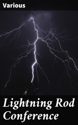
The following three engravings render very few verbal details necessary. Fig. 1 gives the east elevation of the castle, it shows part of a flag-staff 115 feet high, which has a conductor, also three of the principal terminals, and twenty-six minor points upon the building, and by two dotted lines the position of two of the main conductors to earth. The principal terminals are tapered iron tubes, 13 feet long, carrying copper tapes 1 inch × 1/16th and terminating with copper points tipped with platinum; the minor points are of solid copper 9 inches long. The main conductors to earth are copper tapes 2½ in. × 1/16th.
Fig. 1.
Fig. 2 give a plan of the roof, much of which is of glass with wooden rafters. The twelve principal terminals are shown by small rings, the ninety-four minor points by round dots, the horizontal copper tape (2 inches × 1/16th), uniting all the upper terminals, by a pecked line, and the position of the main conductors to earth by dotted crosses. All the gutters are metallically connected with the conductors.
Fig. 2.
Fig. 3 gives a general plan (for which we are indebted to the architects, Messrs. T. C. Hine & Sons) of the castle and grounds, and also a little section indicative of the precipitous eminence on which the castle stands. From these it will be seen that two of the main conductors to earth are carried underground at a depth of about 4 feet, under the terrace and down the slope and terminate in trellis-work, about 14 feet square, of 2½ inches × 1/16th copper tape rivetted at every intersection. The other earth contact is obtained by bolting the terminal on to the town water-main. The total length of tape used in the earth connections was about 500 feet.
SANDERSON & CO.
Fig. 3.